-
There are a couple of ways but it sounds like you didn't dimension the profile sketch to the rotational axis for some reason so that's the direction I would go.
First, pick something in the profile to use as a reference for all the other geometry. I did this on my version of your sight model;
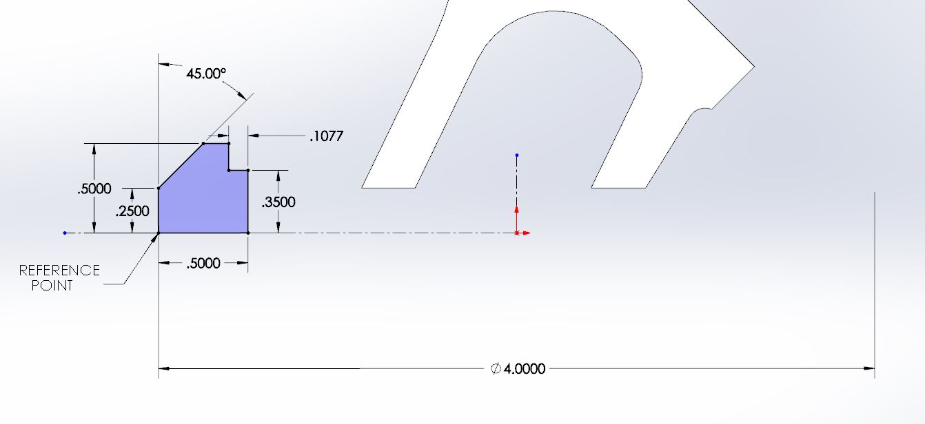
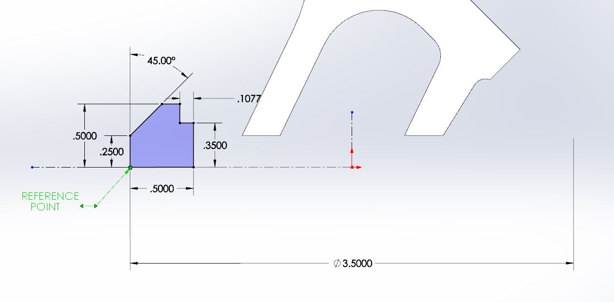
The profile is fully defined and the reference point is horizontal of the origin (I added a horizontal centerline from the origin the illustrate this). The .250 vertical line defines the outside face of the profile and is dimensioned as a diameter from the vertical centerline at the origin. In the second image I edited the 4" diameter to 3.5" to move the profile closer to the vertical C/L which is the rotational axis.
 Posting Permissions
- You may not post new threads
- You may not post replies
- You may not post attachments
- You may not edit your posts
-
Forum Rules


 Reply With Quote