-

Vision Microsystems EPI-800 & VM1000 Displays: LCD Precautions & Black Ooze Failures
This is the 5th in a series of posts about the Vision Microsystems (VMS) VM1000 and EPI-800 engine management systems. As a reminder, I’m not a FAA certified avionics technician, and I don’t consider myself a VMS guru, just an avid experimental aircraft enthusiast and EAA member passing along what I’ve learned to the community that’s given so much to me. I have learned a lot over the years providing repair and support services to the VMS owners and operators. This post will cover the liquid crystal display (LCD) element in the EPI-800 and VM1000 displays and how to avoid the dreaded “black ooze” failure.
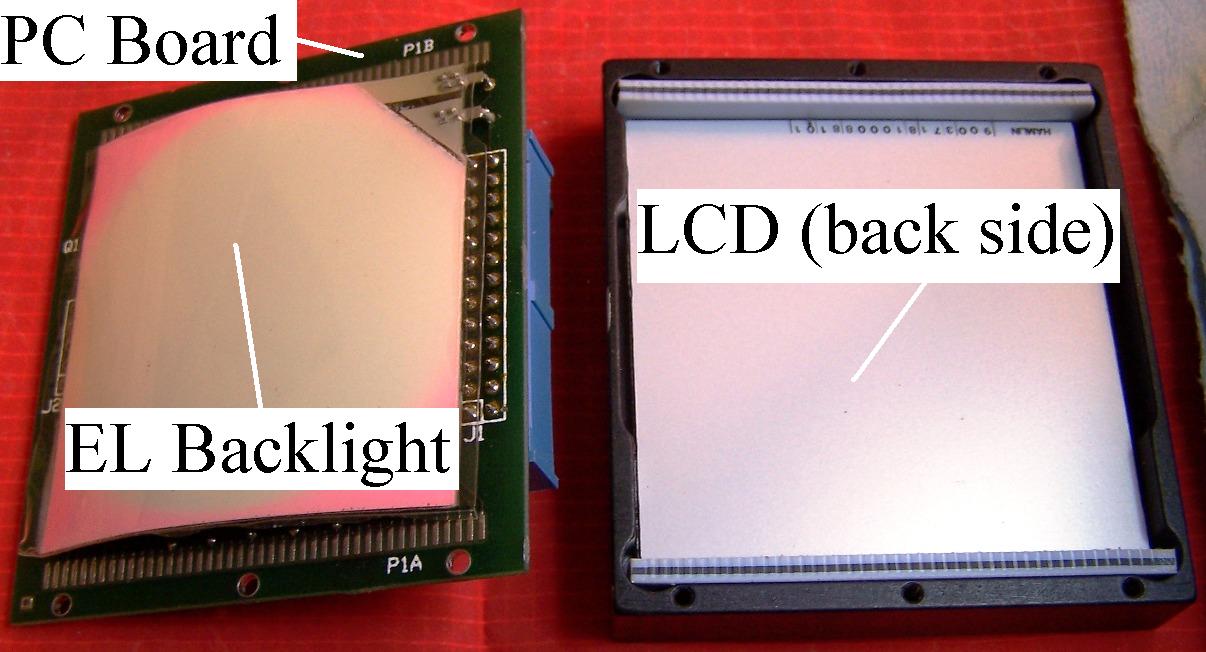
First, here is some basic information on how the displays operate. VMS indicators consist of 4 basic components, the PC board with necessary support chips, the electroluminescent (EL) backlight panel, and the LCD screen, plus the aluminum frame or bezel (see picture). All VMS owners are familiar with the display ribbon cable and rectangular connectors that join the data processing unit (DPU) with each of the individual display units (DU). Data from the DPU flows to the DU where it is translated by onboard chips within the DU case into electrical pulses and routed to the correct LCD elements. Each of the correct LCD elements darkens as they are electrically stimulated and the operator has a crisp display of engine information. The system is lightweight with low power consumption and great readability in daylight conditions. The addition of an EL backlight adds practical night time readability to round out a reliable, lightweight, and robust indicator.

Picture 1. Components of the VMS display (EPI-800 indicator pictured).
While the LCD is one of the indicator’s best features, if abused it can also be the downfall. I’ve seen a rash lately of indicators with failed LCD screens … not because of old age, or harsh service, or lots of usage. The failures I’ve seen are all installer/remover induced and are completely preventable.
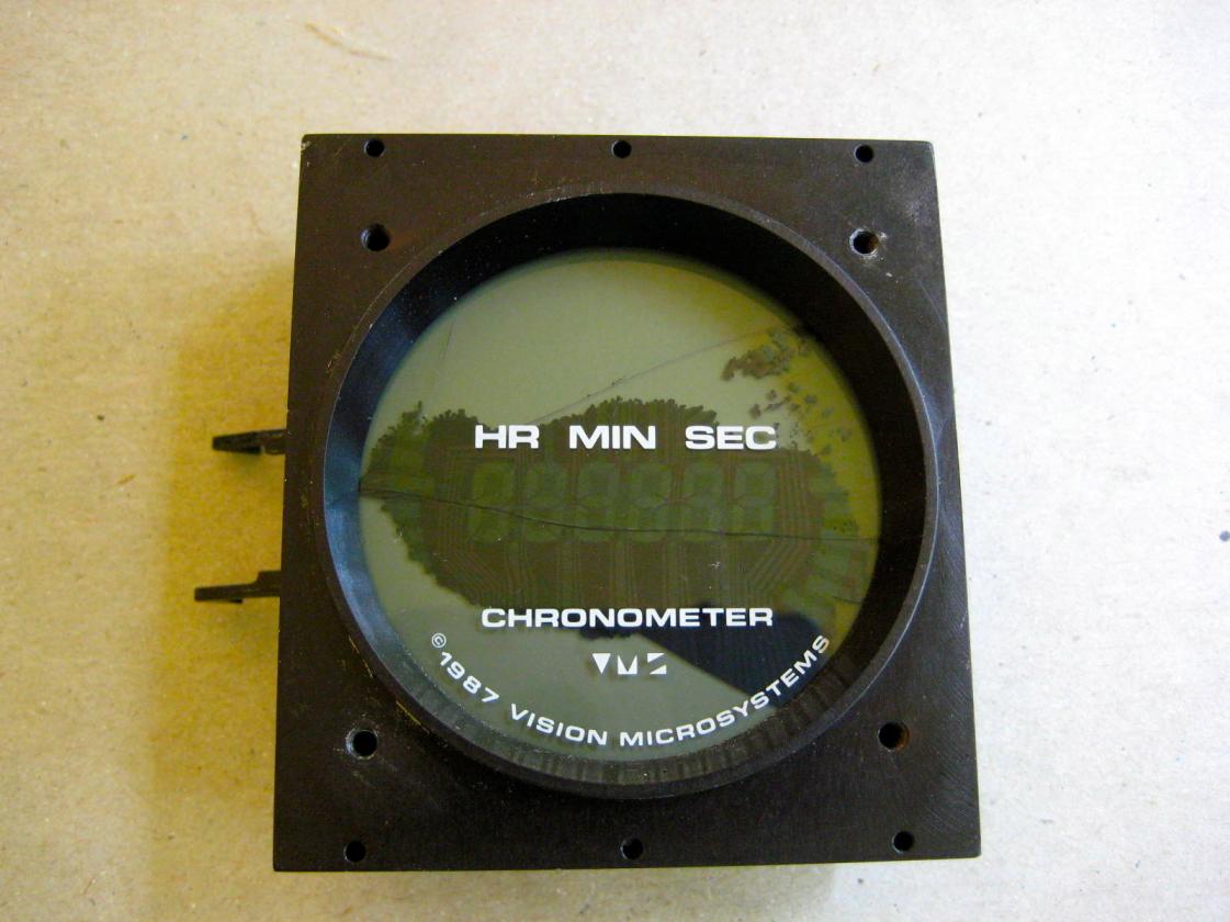
In one case, the installer was drilling through the flange of his instrument panel to add some mounting hardware. He had spent a lot of time building up his panel and had pre-installed his VMS indicators (yes, believe it or not there are still builders out there with new/unused VMS units that originally came with their kit aircraft and they are just now finishing their kits and installing the systems) … unfortunately he forgot about one of his indicators close to the flange, drilled all the way through the side of the aluminum frame and into the edge of the LCD screen just enough to crack the glass and disturb the crystal matrix. Result was the “black ooze” failure in which sections of the LCD screen turn black along the crack lines, when you touch those areas they appear to “ooze” with your finger movement (see picture 2). He sent me the indicator lamenting his mistake and asked if it could be fixed … unfortunately he damaged the aluminum frame too badly to be reused but I found a serviceable one, reused his display PC board and backlight, replaced the LCD with a new screen, and it worked good as new. Word to the wise, don’t drill into your VMS products!

Picture 2. Cracked LCD screen showing "black ooze" failure.
In another case an owner was removing his VM1000 display to send to me for a backlight replacement. After more than 15 years in his panel, the display did not want to come out easily so he succumbed to temptation, pressed on the front glass firmly and heard the sickening sound of the LCD glass crack … moving his hand away the “black ooze” had already spread over the lower half of his display. One can only imagine the string of expletives that must have followed! So, instead of a just a backlight repair, he got a new LCD screen as well … but hey, now the indicator literally looked and worked like brand new!
So how do you safely remove a display that has become attached (so to speak) to your aircraft? Rule number one, under no circumstances should you press on the LCD glass. Rule number two, re-read rule number one! If you have removed all the bezel screws and the display is still firmly attached to your panel, reinstall each of the screws just a couple of threads. Press firmly on the screw head to loosen the display, be sure to have a hand or towels or some means of caching the display should it pop out behind the panel. On EPI-800 indicators, you can also press on the black part of the bezel that extends beyond the LCD screen through your panel. On VM1000 displays, you can also use your buttons along the bottom of the display for some leverage to press on. If you can reach behind your panel to the display frame, that is the best way to loosen it, pulling rather than pushing … however, I realize on many installations this is not possible.
Hopefully this article will help preclude the dreaded “black ooze” … but if you should find your display drowning the dark matter, please feel free to contact me. If I can help with any Vision Microsystems issues you can email direct at mooney37v@juno.com
Happy Flying,
Reggie
Last edited by Glas467; 10-02-2013 at 05:29 PM.
Reason: added picture
Tags for this Thread
 Posting Permissions
- You may not post new threads
- You may not post replies
- You may not post attachments
- You may not edit your posts
-
Forum Rules


 Reply With Quote
