Page 1 of 2 12 LastLast
Results 1 to 10 of 12

Thread: I need some help with longerons

  1. #1

    Join Date
    Jun 2020
    Posts
    5

    I need some help with longerons

    So I知 really new to solidworks. I had zero experience in cad previous to this. I知 trying to draw a pa18 fuselage out so I can have the tubes laser cut. I have everything sketched out but when I add the weldments to the longerons it痴 not all one long tube. Is there something I知 missing? Or a way to make all the sketch lines one piece so the tube will be all one piece?
    sorry it this is confusing.

  2. #2
    SOLIDWORKS Support Volunteer Jeffrey Meyer's Avatar
    Join Date
    Nov 2011
    Location
    Israel
    Posts
    215
    Hi.
    I assume your sketches are splines?
    If so, it could be a simple display problem.
    One way or the other could you show us a screen shot?

  3. #3

    Join Date
    Jun 2020
    Posts
    5
    They are not splines. Should they be? I uploaded a screenshot I had on my phone. Once I locate my power cable for my laptop I can upload a better one. Thanks for the response.
    Attached Images Attached Images  

  4. #4
    SOLIDWORKS Support Volunteer Jeffrey Meyer's Avatar
    Join Date
    Nov 2011
    Location
    Israel
    Posts
    215
    Ok - the screen shot looks just fine, but I'm still trying to understand your problem and your expectations.
    Obviously the longerons are curved - that's why I asked if they're splines. So now the question is if you want to make them out of curved (spline) tubes, or straight pieces between the welds? I'm not sure if the SW weldment features work with splines (logic says it should) but I haven't tried it. If it doesn't, you might have to be happy with straight pieces between the welds, or don't use the weldment feature.
    Maybe someone out there has more experience than I.

  5. #5
    cwilliamrose's Avatar
    Join Date
    Nov 2013
    Location
    SW Florida
    Posts
    217
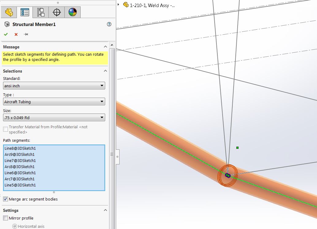
    The formed longerons are (or should be) a series of straight sections with small radius bends at the clusters where the longeron changes direction. Your sketches defining the longeron's path will be a series of lines and tangent arcs. When you select the path for the longeron you select in order those lines and arcs and the result is a continuous tube.
    Name:  Longerons in SWx1.JPG
Views: 1148
Size:  86.0 KB
    Here you see the selections I made to create the lower longeron. The radius of the arcs should all be the same and they need to be about 1x the diameter to be realistic. If the radius is too small the feature will fail to complete.
    Name:  Longerons in SWx2.JPG
Views: 1090
Size:  96.3 KB
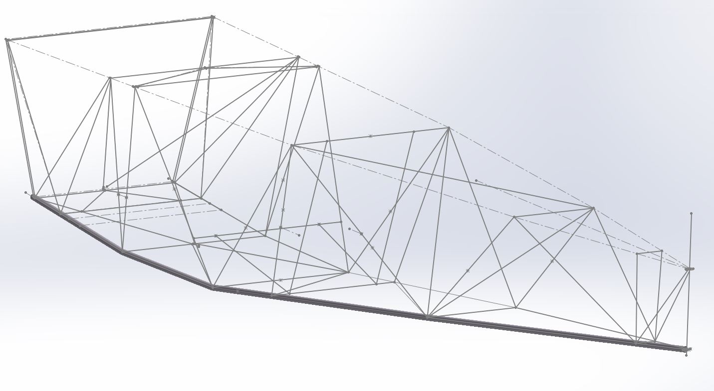
    Here's a view of the entire longeron.
    Name:  Longerons in SWx3.JPG
Views: 1131
Size:  72.0 KB
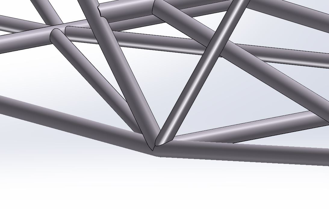
    This is a close-up of the structure showing a cluster where the longeron is bent and the trimmed tubes meeting at the bend.

    ...........Bill
    Last edited by cwilliamrose; 06-11-2020 at 07:04 AM.

  6. #6

    Join Date
    Jun 2020
    Posts
    5
    Quote Originally Posted by cwilliamrose View Post
    The formed longerons are (or should be) a series of straight sections with small radius bends at the clusters where the longeron changes direction. Your sketches defining the longeron's path will be a series of lines and tangent arcs. When you select the path for the longeron you select in order those lines and arcs and the result is a continuous tube.

    Name:  Longerons in SWx1.JPG
Views: 1148
Size:  86.0 KB
    Here you see the selections I made to create the lower longeron. The radius of the arcs should all be the same and they need to be about 1x the diameter to be realistic. If the radius is too small the feature will fail to complete.

    Name:  Longerons in SWx2.JPG
Views: 1090
Size:  96.3 KB
    Here's a view of the entire longeron.

    Name:  Longerons in SWx3.JPG
Views: 1131
Size:  72.0 KB
    This is a close-up of the structure showing a cluster where the longeron is bent and the trimmed tubes meeting at the bend.

    ...........Bill
    ok thank you bill. I’m going to try to figure out how to do this. I’m kinda lost. I am enjoying learning solidworks though. It’s something I’ve always wanted to know how to use

  7. #7
    cwilliamrose's Avatar
    Join Date
    Nov 2013
    Location
    SW Florida
    Posts
    217
    If you have questions just ask.

    For a start just open a regular (2D) sketch and draw two lines and fillet between them. Then use those to draw a bent tube.

    For my lower longeron I used a 3D sketch because the longeron's centerline cannot reside in one plane.
    Last edited by cwilliamrose; 06-12-2020 at 08:03 AM.

  8. #8
    vondeliusc's Avatar
    Join Date
    Nov 2011
    Location
    Kalispell, MT
    Posts
    41

    Lightbulb Reality vs perfection

    Bstrop-
    First, might I suggest you sign posts with your name.
    It would be helpful to know if the longerons are planar, or
    are or varying in width spacing and non-linear height?
    Doing as Bill suggests using 3-D sketches for non-planar longerons including realistic bend radii,
    will yield the best accuracy, but a laser cannot cut concave, only cylindrically;
    in my build up of a non-planar longeron (left example) I have used a 1.5" bend radius,
    which yields a .44" length outside arc. I think you are better off to use straight lines,
    point to point, to simulate the longeron, even if non-planar. This way, it is straight-forward to
    give the data to the laser as the ends of tube intersections will all be cylindrical.
    Otherwise, the ends of the nesting tubes will have SW generated concave ends.
    In my top view of examples, there are two ways to create the structural intersections:
    The one is the middle example, with tube bends normal to each section, and the
    RH example is using the 'apply corner treatment' which co-miters each bend (w/o a radius).
    The radii should be fairly insignificant so personally I would draw it with the co-miter corner treatment
    at bends on the longeron to be able to export 'realistic' data for laser purposes.
    When you go to fit the parts, they may require a minimal bit of grinding to fit the 'real-life' bends
    in the longeron, but considering the small errors involved, you should be good to go.
    Draw all intersections as point to point with lines for the structure in the laser version,
    and you could have an over-laid version which incorporates the true bends to create a drawing for
    bending the longerons; that said it all will depend on how accurately the longerons are bent in real life.
    Strictly my opinion.
    -Christian

    Attached Images Attached Images  
    Last edited by vondeliusc; 06-12-2020 at 05:15 PM.

  9. #9

    Join Date
    Jun 2020
    Posts
    5
    Thanks Christian,
    I guess the bends in the longerons are not really that important as I was thinking. I'm not going to have them cut on the laser. I don't really want to ship four 18ft pieces of tube across the country ha. I will try your suggestions and report back. I've attached my drawing If you want to take a look at it
    Thanks again
    Brian

  10. #10
    vondeliusc's Avatar
    Join Date
    Nov 2011
    Location
    Kalispell, MT
    Posts
    41
    Brian-
    Yup, you probably will need to break them to about 6' for cheap shipping. I would suggest at least an inch extra since most cuts by sellers are dubiously accurate.
    Also, since you have a model, you can pick where you want the joints to be. Using 0.049, inner sleeving will be a bit sloppy; if you use 0.058 as an outer sleeve,
    it will sleeve snugly over the next 1/8" size down (0.875 x 0.058 over 0.75) and I would guess about 2-3 tubing diameters each side for the sleeve (say 6").
    There was no attachment to the post, btw, because I would have liked to take a look.
    -Christian

Posting Permissions

  • You may not post new threads
  • You may not post replies
  • You may not post attachments
  • You may not edit your posts
  •