Page 14 of 18 FirstFirst ... 41213141516 ... LastLast
Results 131 to 140 of 173

Thread: Norm's Flying Boat UL Flight Test Progress

  1. #131

    Join Date
    Jan 2012
    Posts
    302
    Quote Originally Posted by Norman Langlois View Post
    New floats applied I hope the differences are all positive. The others originally tapered going aft then needed the upper 2 inch deck to have enough displacement to be stable. They became heavy,15#. These have more displacement and weigh less than 8# with the support frame , bare no fiberglass Attachment 7183Attachment 7184
    I like the rear float design with no bottom curved surface. It could possibly be improved with a step at the angle break. Keep that edge sharp, not rounded. Hope that works for you. If needed I can make further suggestions.

    Tell is more about the wheeled cart. Is it ground handling only?
    Last edited by jedi; 05-11-2018 at 11:35 AM.

  2. #132
    Norman Langlois's Avatar
    Join Date
    Jul 2011
    Location
    Northwood ,N.H. USA
    Posts
    180
    Jedi to answer your question. The cart is for ground handling. It can be used for launch. It was used for that in the beginning. It was three wheel then and was unstable with wind conditions.
    I use the special trailer for direct launch and the cart is used to move from the trailer to the hanger (garage)
    If Oshkosh 18 is made possible for me. I will need to bring the cart ,the launch trailer will not be there with me.

    On the float I hope no additional step is required.The floats will quickly be above water.

  3. #133
    Norman Langlois's Avatar
    Join Date
    Jul 2011
    Location
    Northwood ,N.H. USA
    Posts
    180
    Update . Things are not going as planned. I think Oshkosh is not going to happen. If I go it will be just as a spectator.
    The new floats are almost finished. I get my car back next week and maybe by the week after.Name:  left side  new flts.jpg
Views: 1393
Size:  94.6 KBName:  new rr flts.jpg
Views: 1354
Size:  90.6 KB I can get to the lake for a test flight. A little paint and out the door for inspection setup and run up.

  4. #134
    Norman Langlois's Avatar
    Join Date
    Jul 2011
    Location
    Northwood ,N.H. USA
    Posts
    180
    I have posted those new photos. I took care to center the camera level with the top of the floats and leveled out the airplane. The piece of conduit across show the relation . So I can see that they are almost at the same elevation as the older setup. I detect that the old setup may have had the lower tube brace dragging in the water when the plane jacked before on plane was achieved. This new setup is 1 inch higher and there is more displacement and should be above water even when jacked back fore the thrust up on plane.
    When the bow wave develops.There is a steep up angle this has not been a problem .I only hope with the increase of displacement. This does not result in a nose down drag by creating some incompatible relation to the main hull. This has been very tricky . I still don't understand why that after portion on the main hull was so important.

  5. #135

    Join Date
    Apr 2018
    Posts
    66
    Norm I have been reading all this and I am so impressed. My thought and its stupid I know, my wife uses a commercially built kayak that is maybe 11 ft long, poly something plastic and very tough and light. If a person was to put a internal keel/brace inside on the bottom and aluminum attachments like you have fab above and spray foamed filled. One of these floats on each side and these are made to flow very easily in the water. Just a thought and you already have these done.

  6. #136
    Norman Langlois's Avatar
    Join Date
    Jul 2011
    Location
    Northwood ,N.H. USA
    Posts
    180
    wmgeorge
    Thank you for your reply.
    Over the years many suggestions have been made. One notable was that round surfaces where not good for aircraft floats.
    I had round floats for the rear. They behaved very badly and thus I was told to pursue. shapes that had sharp edges and abrupt ends . as on a wing tip when air migrates to the top of the wing lift is lost. a similar bad happens the water also migrates around and this relates to a suction . From Jedi's post he suggests maybe a step. This would help reduce any suction.
    Putting aside these suggestions. I would like to make this point. I have been convinced in my own mind that ultra light aircraft ,having a low take off speed. Do not need to adhere to the strict requirements of heavy general aviation seaplanes. these need a much faster take off speed. that means a much higher hydrodynamic drag ratio. The multiplier is not linear with aerodynamic drag. The suction that hold the hull and requires steps and air induction in some cases . Is not as relevant to ultralight aircraft. I be leave the my craft shows this to be so. I once related my conclusion to the the weight shift that used a zodiac hull and still lifts off. Round sided and no step. It still lifts off,maybe not as well.
    Using a Kayak hull could fly . The FAA allows 30# exemption for each pontoon and 10# for each sponson and only 30# for a hull
    Even though the Kayak plastic hull feels light it probably weighs close to the exemption. The addition of foam and structure would make it undesirable. If the air frame weight even allowed this option.
    If I remember I started with a complete air frame weight of around 240# I realized I was not going to make a wheeled ultra light and deviated toward the seaplane. Removing all the gear structure nibbling away I have always been restricted from many suggested solutions because of weight. The use of more resin to smooth surfaces has always been out of the question since resin is very heavy again hydrodynamics are less of an concern because of lift off speeds. I have used resin and glass to seal out water and give the foam a thin skin .Also taking care to use less fiberglass and resin for structure. and using tubing instead. I also opted for solid core when I could .High density in combination with low density where possible. The high density for external glassed surfaces and low density internal. The main hull has a fiberglass spine, and contains no aluminum skeleton other than the air frame junction.

  7. #137
    Norman Langlois's Avatar
    Join Date
    Jul 2011
    Location
    Northwood ,N.H. USA
    Posts
    180
    Name:  127_0198.jpg
Views: 1255
Size:  92.6 KB I threw some paint on them. It shows the water line in blue. These should work well now I need to get to the lake .
    Attached Images Attached Images  

  8. #138

    Join Date
    Apr 2018
    Posts
    66
    Norm thanks for the well thought out answer. I figured someone you or someone else had already covered those float. Your work on this project is a pioneering step forward and I think you have done a great job of getting it airborne!

  9. #139
    Norman Langlois's Avatar
    Join Date
    Jul 2011
    Location
    Northwood ,N.H. USA
    Posts
    180
    I did not take the plane to the lake. Instead I had it weighed and found that over time, with all the hack and chop,water weight gain and a few add on for improvement, had become seriously over. Water is responsible for most of it. Some is dirt accumulation. the rest just plain extras.
    I am now recalculating and a new hull is mandatory . Weight distribution will also need adjustment. I doubt it will fly again this year.
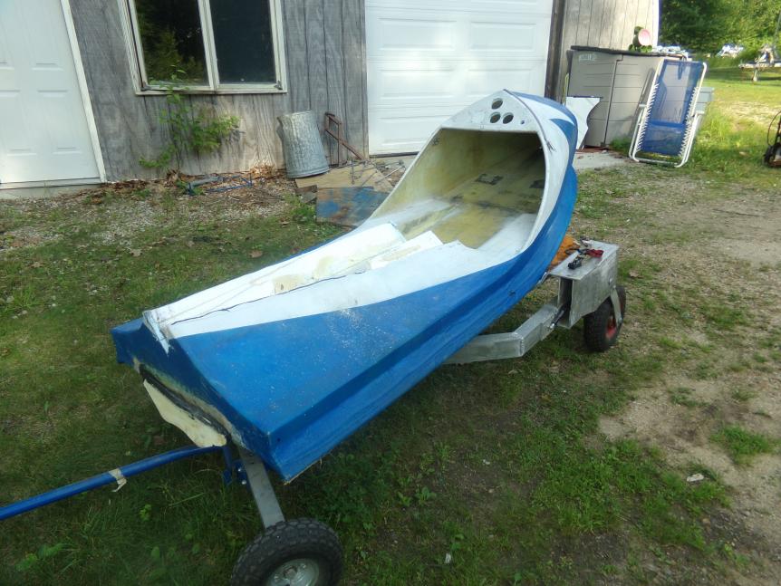
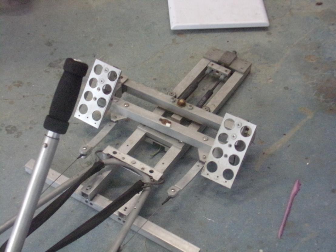
    I cut the hull off and removed the luxury pedals they are 10# the hull went from 45# to 60# I have to find and remove 58#
    That means a new hull of less than 30#Name:  127_0201.jpg
Views: 1161
Size:  95.9 KBName:  127_0204.jpg
Views: 1176
Size:  88.3 KB
    Last edited by Norman Langlois; 07-01-2018 at 07:09 AM.

  10. #140

    Join Date
    Jan 2012
    Posts
    302
    Quote Originally Posted by Norman Langlois View Post
    I did not take the plane to the lake. Instead I had it weighed and found that over time, with all the hack and chop,water weight gain and a few add on for improvement, had become seriously over. Water is responsible for most of it. Some is dirt accumulation. the rest just plain extras.
    I am now recalculating and a new hull is mandatory . Weight distribution will also need adjustment. I doubt it will fly again this year.
    I cut the hull off and removed the luxury pedals they are 10# the hull went from 45# to 60# I have to find and remove 58#
    That means a new hull of less than 30#Name:  127_0201.jpg
Views: 1161
Size:  95.9 KBName:  127_0204.jpg
Views: 1176
Size:  88.3 KB
    I and a few friends would like to help with hull design if logistics can be worked out. Can you give some specifications on hard points and other limitations / requirements.

Posting Permissions

  • You may not post new threads
  • You may not post replies
  • You may not post attachments
  • You may not edit your posts
  •