


It was originally intended to be a single part. However, my printer didn't like the overhangs, and the slicer added a bunch of supports which are just too involved to try to clean up.Originally Posted by cwilliamrose

I then went to a second version where the vertical parts were split in two.... a lower section that went into the circular base and barely stuck out above it, and a separate upper portion. That printed very nicely. However, I did re-slice the original single-piece part and turned off the automatic supports. The printer did quite well. Left some bits of plastic slag at some edges, and the arcs as the bottom of the verticals are a bit rough. Should clean up OK with sandpaper and files. Not SW's fault, it's just a limitation of the printer.
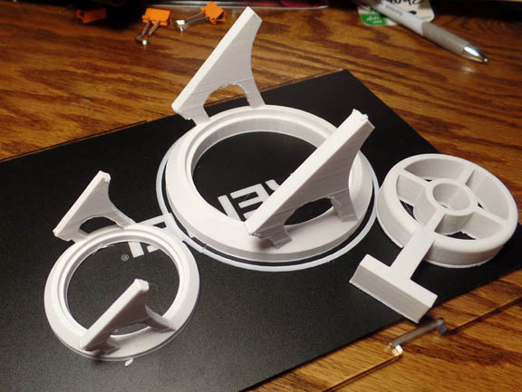
This picture shows the final version, a half-scale one that I tested first, and an old-school sight that was my actual first attempt at 3D modelling using the SW tutorials. The flaws I mentioned in the verticals are visible.
Thanks much. Looking into that gave me a lot of insight into how to do it better.
I think this is a by-product of importing the vertical pieces as a DXF. The original was a polygon with line segments simulating curves, and it imported with a lot more entities than were needed.
At the time, I didn't realize one could "cascade" sketch features (add arcs to a polygon, for instance) and hadn't figured out (yet) how to edit sketches. Took me a day or so to discover and learn how to exploit the edit modes. Fiddling with your drawing, I see better how they work. Some of my 2D drawing experience is messing with me a bit; need to make the mental switch to the idiosyncrasies of Solidworks.
Your other suggestions are appreciated; I'll do more poking around to try to get better.
Hate hassling you, but do have one question: Say I have a hard copy of a line drawing, such as the side view of an airplane. I can scan it in easily enough, and would like to import it into SW and use sketch to outline it to turn it into a SW drawing. How do I do the import?
I have a gazillion other questions, but I probably learn more fumbling and poking around.
Thanks again....
Ron Wanttaja

 Reply With Quote