Page 5 of 21 FirstFirst ... 3456715 ... LastLast
Results 41 to 50 of 209

Thread: Building a Fokker D VII

  1. #41
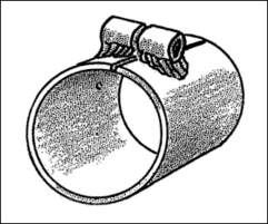
    Welding up a bunch of these little f**kers (Fokkers, bet you thought I said something else) today in different configurations and tubing diameters. 1mm steel has a habit of blowing big holes when you start to weld on it. At least the ferule is 1.5mm so you can focus most of the initial heat on that piece.
    Name:  Fok fokker clamp.jpg
Views: 1194
Size:  9.1 KB
    Last edited by Fokker Builder; 04-11-2017 at 07:34 AM.

  2. #42

    Join Date
    Aug 2011
    Location
    Alabama
    Posts
    2,236
    While I'm also following this build over on the Aerodrome site, I'll use this one for the ignorant questions while the historical experts help on the other.

    Namely, what are these clamps used for? To the uneducated, they don't look to do anything, as they go around a single tube.
    The opinions and statements of this poster are largely based on facts and portray a possible version of the actual events.

  3. #43
    Frank and anyone else reading,

    These are called the Fokker or Dutchman clamp. They allow attachment of almost anything to a piece of fuselage tubing without welding mid span. Since welding mid span would weaken a piece of tubing this was an ingenious invention in 1918 by Anthony Fokker or one of his subordinates. There was an article written by Budd Davisson, in the August issue of, Experimenter,that tells how to make these.

    The clamp pictured above would be a simple clamp that you could bolt a flange or tab to. Combine this with another piece of tubing and you could make a bearing housing that locks another piece of tubing in position. yesterday I had been making these with a TIG welder and becoming more proficient with only one blow out. Someone from the Aerodrome suggested using a torch here and I like the results.

    Happy hunting
    Fokker Builder
    Last edited by Fokker Builder; 04-12-2017 at 02:21 PM.

  4. #44
    4/14, I have some pics to show you guys from this last week.
    First couple pics are of the control column, yoke area, torque tube, and rudder bar post area. There are 11 Fokker clamps used to assemble all this. Everything is rough right now for pre-assembly. It will get taken apart, cleaned up, an etching primer and then some Fokker green. Still have much more to do as usual in these projects this was a first piece. It may all get redone.
    Name:  Fok control column cockpit controls.jpg
Views: 1111
Size:  93.6 KB
    Name:  Fok rudder bar column.jpg
Views: 1051
Size:  94.5 KB

    Third Pic is of all the rudder bar parts after fabrication. Sunday it will get welded if I have time. We are celebrating Easter tomorrow at moms and Sunday I am spending the day with my wife.
    Name:  Fok rudder bar parts fabricated.jpg
Views: 1067
Size:  94.7 KB

    Fourth pic is the bending fixture for the foot pedals and cross braces. The drawing called for 8mm X 1mm for the bent pieces but I used 10 X 2 (I didn't have the 8 X 1).
    Name:  Fok rudder bar bending fixture.jpg
Views: 1025
Size:  92.6 KB

    Working at it a little most days. Today was a good day.
    Chasing Camels
    Jim

    Last edited by Fokker Builder; 04-15-2017 at 07:05 AM.

  5. #45

    Join Date
    Aug 2011
    Location
    Alabama
    Posts
    2,236
    Trial assembly!

    w00t!

    I actually really enjoyed the initial fitting, as it really makes the plans jump to life and things get really clear. Then the little adjustments before final assembly.
    The opinions and statements of this poster are largely based on facts and portray a possible version of the actual events.

  6. #46
    Thanks Frank

    4/16, Easter Sunday. Welded up the rudder bar and started carving the control column handle. No Dremell there baby as I prefer the carving tools on mahogany. These two handle halves will get epoxied to each other around the tubing and get a brass rivet or two through the handle tubing.
    Name:  Rudder bar welded 2.jpg
Views: 1054
Size:  93.4 KB
    Name:  Control column handle.jpg
Views: 1016
Size:  94.2 KB


    I think later this week I will surface prep the rudder bar, control column, and torque tube parts for a coat of etching primer.


    End of the week I hope to start welding in all the wire loops in the corners of the fuselage clusters so I can start heading towards priming the fuselage later this spring.


    Peace

    Jim

  7. #47
    bookmaker's Avatar
    Join Date
    Nov 2011
    Location
    Florida Panhandle
    Posts
    209
    Coming along nicely Jim.

    Dale
    Dale Cavin
    Florida Panhandle
    Current Project: Airdrome Aeroplanes Full Size Nieuport 17

  8. #48
    Thanks Dale

  9. #49
    4/21 - 4/23, Here are 3 pics of the 54 wire loops I was working on for 12 hours over the last three days. Also included was a gas welding rig I fabricated out of an old dolly and I was tightening up the welding on all the tubing clusters. Till I ran out of oxygen in the new used oxy/acetalene rig I got off Craigslist last week.
    Name:  Fok wire loops 1.jpg
Views: 964
Size:  93.7 KB
    Name:  Fok wire loops 2.jpg
Views: 872
Size:  91.0 KB
    Name:  Fok wire loops 3.jpg
Views: 956
Size:  94.2 KB

    The welding cart I cut the top off the dolly and welded up a new handle from some of my 30 mm tubing, a bent piece of 13 mm, some 1 mm sheet for the hose rack, and a couple nuts so I could thread in bolts for the chain keeper. Took all of 60 minutes and then sprayed it with some etching primer. I love making the shop more functional.
    Name:  Fok welding cart.jpg
Views: 951
Size:  92.5 KB

    Peace
    Jim


  10. #50

    Join Date
    Aug 2011
    Location
    Alabama
    Posts
    2,236
    Pretty danged neat!
    The opinions and statements of this poster are largely based on facts and portray a possible version of the actual events.

Posting Permissions

  • You may not post new threads
  • You may not post replies
  • You may not post attachments
  • You may not edit your posts
  •