-

Modeling the Internal Structure of a Flap Assembly
I've been modeling various parts of my Super Chipmunk as a way to learn SolidWorks. I'll play with a new design after I build some essential skills. I modeled the entire airplane as a single part before I realized how dumb that is, then started building more complex assemblies like landing gear to sit it on. The upside of doing this dumb thing is that I now have a fully lofted, integrated airplane with everything in the right spot and shape relative to the other parts (eg, wing, stab, fuselage all in the right relationship with each other).
The next challenge is to learn how to build from the outside-in. There is no way I'll model the whole plane - it's become clear now that I could work on it the rest of my life and never finish! I just need to do a few assemblies as learning aids. So I picked the right flap as a case study. Once the flap itself is "in hand" I'll use Layout to map out and test the whole operating system of cables, pulleys, hinges and flap handle.
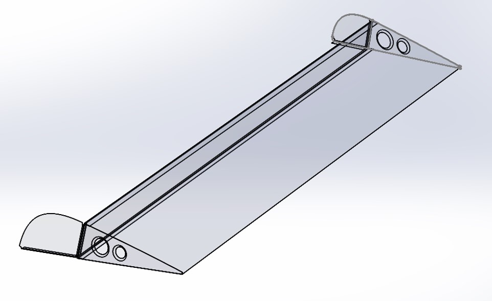
Below are pics of what I have so far. It's posted on GrabCAD with the EAA handle.
To start, I split the flap from the rest of the airplane and saved it out. Then built the two end ribs from that using Convert Entities and Offset Entities to get the rib shape. The nose rib assumes .032 sheet, the tail .025, and the spar bent from .040. Goal is to use SWx Sheet Metal as much as possible, so the parts could be flattened and printed to use as cut templates.
This has been a bear to figure out, and very time consuming. I understand the popularity of hershey bar wings for RVs and Pipers - it would be SOOOO much easier to model and actually build than a tapered wing (and flap) like on a Chipmunk. The taper makes every angle different. It also means I need to figure out the shapes of each rib and model each one separately. Doing this for a whole wing (or fuselage, or stab...) using the methods I've used so far would be scary-time-consuming!
Is there a better way, or is this just the way it is? I'd appreciate insights! Things that don't work well in my model:
1. Rib flange angles are just eyeballed on the screen. They're good enough to build a form block then do the fine tuning like any builder knows how to do using fluting pliers or a shrinker machine, but they would never be good enough for SWx mates with the skin sheets (or ribs against the spar). Not that it matters that much if they mate, but it seems unprofessional to have parts that clearly don't fit perfectly.
2. Curved Flanges. Only the straight parts of the sheet metal (ribs and spar) are flanged, not any curves. I should be able to do a swept flange for the curved nose ribs but have not made SWx cooperate (even though it's easy on the Lynda training parts). Besides, they still wouldn't fit the skin because of the taper which changes the bend angle slightly from the spar to the leading edge. I experimented with making a lofted surface for the flanges (by adding a plane where the flanges end, lofting the whole flap as a surface, then inserting a new loft profile for the edges of the flanges. Then I could loft the flange surfaces and thicken them to .032 or .025.) This worked fine, and they would fit perfectly against the skin, but they're not Sheet Metal! They're just out in space, not part of the ribs, and there is no bend radius in the corners. How do designers make ribs for a tapered wing??
3. Skin Overlaps. I have not added the .032 nose skin yet. Challenge: the overlap with the tail skin at the spar. I suppose I could split then modify the Offset Entities spline at the root and tip to provide the overlap - wouldn't be hard. They could also be joggled (my Chipmunk wing is actually done this way to join the D-nose box with the rest of the wing skin aft of the spar). I've seen how to do joggles in SWx. They could also butted like on an RV wing. But the flap on the actual Chipmunk is overlapped, as are most of the fuselage panels.
4. Skin Sheet Metal. The tail skin is a lofted surface then thickened. Easy. But it's not sheet metal so can't be flattened to make a template. I know there is a way to do this with a surface. I messed with this on the complex curved parts of my fuselage - you can flatten then color code the amount of shrink and stretch to form it. It's kinda cool, and looked similar to the actual forming I had to do to make fairings on the English wheel. The flap skins are simple curves, and this should work. But is this the best way to get a skin pattern? I'd like to have the Drawing capabilites you get with SWx Sheet Metal.
That's enough challenges for now! Appreciate any suggestions. Mark 

 Posting Permissions
- You may not post new threads
- You may not post replies
- You may not post attachments
- You may not edit your posts
-
Forum Rules


 Reply With Quote