-

Vision Microsystems VM1000 & EPI800: What version do I have?
This is the 4th in a series of posts about the Vision Microsystems (VMS) VM1000 and EPI-800 engine management systems. As a reminder, Im not a FAA certified avionics technician, just an avid experimental aircraft enthusiast and EAA member passing along what Ive learned to the community thats given so much to me. This post will cover the different versions and evolution of the VMS product line and provide some tips for keeping each system healthy and reliable.
The first generation VMS system was the EPI-800 with a 1987 copyright date. The data processing unit (DPU) was a screw terminal type that was the blueprint for all subsequent DPUs until 2001 (see pic #1). The first generation DPU had a number of limitations all addressed in later versions. One of the most important aspects of the first gen DPU was that it was not easy to repair because the digital and analog PC boards were hard soldered together via a set of central connection pins in the middle of the DPU case; separating the two boards requires tedious desoldering of the central pins. Also in the first gen DPUs, there are no jumpers. Junctions are hard jumpered via soldered link so changing such parameters as pulse count for magneto vs. electronic ignition RPM sensing is difficult at best. First gen DPUs are generally plagued by delamination issues most commonly on the analog board but can also be found on the digital assembly as well. You can easily identify a first generation DPU by removing the analog board cover (cover with the cutouts for the screw terminals) and look at the pins running from the board into the DPU center. If these pins are flat and covered with what looks like opaque tan masking tape, its a first gen. Dont despair if you have a first gen, they still work fine but may require more labor to repair than later versions.
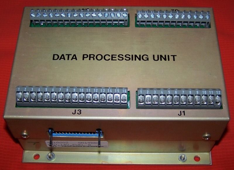
Pic #1: Screw Terminal Type DPU
With the introduction of the VM1000 in the early 1990s, came upgrades to the DPU and starts the second generation. First upgrade was the replacement of hard soldered analog to digital connecting pins, with a header pin and connector setup. Header pins were soldered on the digital board and a receptacle assembly on the analog board (see pic #2). Now the two boards can be easily separated for repairs. However, many of the early VM1000 DPUs still had hard jumpered junctions making changing options in a DPU difficult. It was not until the mid 90s that selectable jumpers were installed on the digital and analog boards starting the third generation DPUs. These final modifications to the boards became the standard configuration until the next major changes in 2001. These 3rd gen boards are identified by © 1992 REV D on the analog board and © 1995 REV H on the digital board. These boards also have high quality etching so there are no issues with delamination as in the first and some of the second generation units.
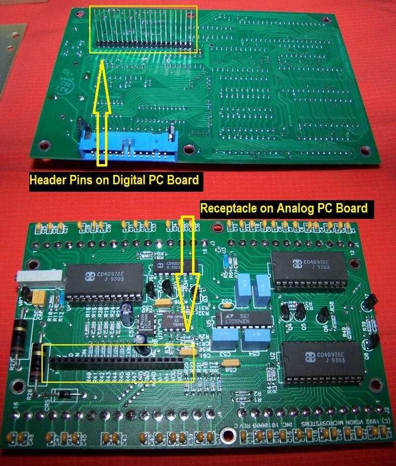 Pic #2: Header Pin and Receptacle Assembly
As owners will attest, screw terminal DPUs have their limitations. In a tight installation, the screw terminals can be difficult to properly torque. Wires have a tendency to loosen or break at the terminals and it is easy to insert the wires too far and clamp down on the insulator instead of the conductor resulting in an intermittent connection and a frustrating time troubleshooting an indication problem. But with knowledge of these limitations, and making the DPU and the screw terminals part of your annual condition inspections, owners can get good service from their systems. A simple torque check using a jewelers screwdriver and gentle tug on each connecting wire should be all thats needed to ensure a good connection.
In 2001, VMS introduced a new version of most of the system components including the DPUs, displays, and sensors for both the EPI-800 and VM1000. The VM1000 also became certified under TSO-C113 and installed in several type certificated aircraft including the Symphony OMF-160 and Liberty XL. The great aspect of this fourth generation is all of the components are backwards compatible with all previous systems. Most notable, on the DPU gone are the screw terminals and are replaced by two serial type connectors, a single 25 pin RS-232 type DSUB connector which handles all the EGT and CHT signal inputs, and a single 37 pin DSUB connector which handles power and all other sensor inputs (see pic #3). This makes for a neat, tidy, and easy to service installation and vastly eases the work required to remove and repair the DPU.
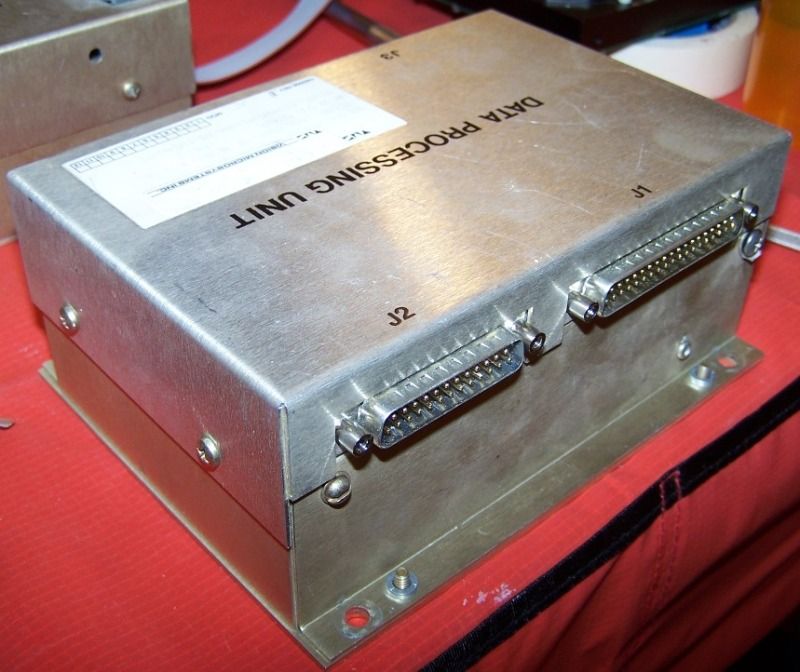 Pic #3: Serial Connector Type DPU
However, installation issues can compromise even this almost bullet proof connection scheme. Many experimental aircraft installations have the ideal geometry where connection cables from the firewall proceed directly into the DPU, a straight connection which induces no side loading on the DSUB connectors. The DPU is installed on the instrument panel with the receptacles facing toward the firewall; these installations typically have no issues with connectivity. Other installations have a 90 degree geometry, cables come into the cabin then turn parallel to the firewall and connect to the DPU. If properly supported, this is also a good connection scheme with little problems. However, fail to properly support the cable runs, and theres a possibility of excessive vibration or resonation of the assembly which eventually results in connections problems at the DPU and resultant display issues in the cockpit. The worst case scenario is illustrated in the Symphony OMF-160 installation in which the signal cables come through the firewall, make a tight radius 180 turn and connect into the DPU with little to no support other than the DPU connection itself (see pic #4). Symphony owners have reported significant issues with display problems traced down to connection issues at the DPU. Vibration and resonation of the cable assembly can wear down the internal pins and sockets inside the DSUB connectors to the point that the contact becomes intermittent and may eventually break the solder joints of the DPU connectors. Check your installation to make sure your signal cables are properly supported and have an appropriate radius for any turns.
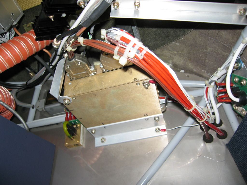 Pic #4: Serial DPU with 180 bend in Cable Connection
The 4th generation systems were also available with some customization not previously available. For example, one version of the VM1000 included a % Power indication in place of the manifold pressure for single lever FADEC equipped aircraft. Another version was setup to output RS232 digital data to GPS units. However, the baseline EPI-800 and VM1000 systems in the experimental market still seemed to dominate the bulk of sales and production with Lycoming O/IO-320/360 series setups for Glasair I & IIs, RVs, two place Lancairs, and many others; Lycoming IO-540 series for Glasair IIIs & F-1 Rockets and Continental IO- & TSIO-550s for the Lancair IVs and many others.
The 4th generation represented the final iteration of the venerable EPI-800 and VM1000 product line ... the next product, the VM1000C was essentially a clean slate design eventually acquired and improved by JP Instruments. If I can help with any Vision Microsystems issues, please feel free to email at mooney37v@juno.com
Happy Flying,
Reggie
Tags for this Thread
 Posting Permissions
- You may not post new threads
- You may not post replies
- You may not post attachments
- You may not edit your posts
-
Forum Rules


 Reply With Quote