-

True Bill
putting a name to the structure that's all. This type of support has worked well for me with the cable brace. It is very light and still resists rotation with the ends bent as they are they form 3 torsion tubes with the spreaders limiting deformation while still allowing some flex . the new one will also make use of torsion bar/tube configuration with the three members coming to the same plane. with complex bends. Then joined to the tube skeleton that is embedded in solid foam . these floats with there supporting structure weigh less than 10 lbs each.
I have been fortunate to have use of a stick mandrel tube bender this can make 4 sizes up to 7/8 and bend 180 degree with no heat required.
I used the anneal process for a lot of the build. One of the toughest bends is a 1 inch .062 tube had to always heat before bending. I found the ink worked well as the indicator, but still better when using the propane torch, I lost a few parts using high heat devices, was much harder to detect over heating.
The lighten holes that are also coined are cold pressed. The bending of sheet limited to 60 degrees eliminate other wise cracked structure since 6061-T6 does not bend well at 90 and greater . If I do another air frame I plan to use a 6 sided structure . Unlike the boom and spar having \_/ this shape . It will use three short and 3 long still forming the triangle with one main side riveted and joined at two shorts. I also taper my structure , both to reduce weight and to add torque resistance.
-
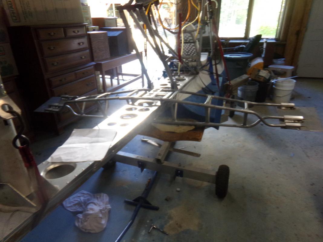
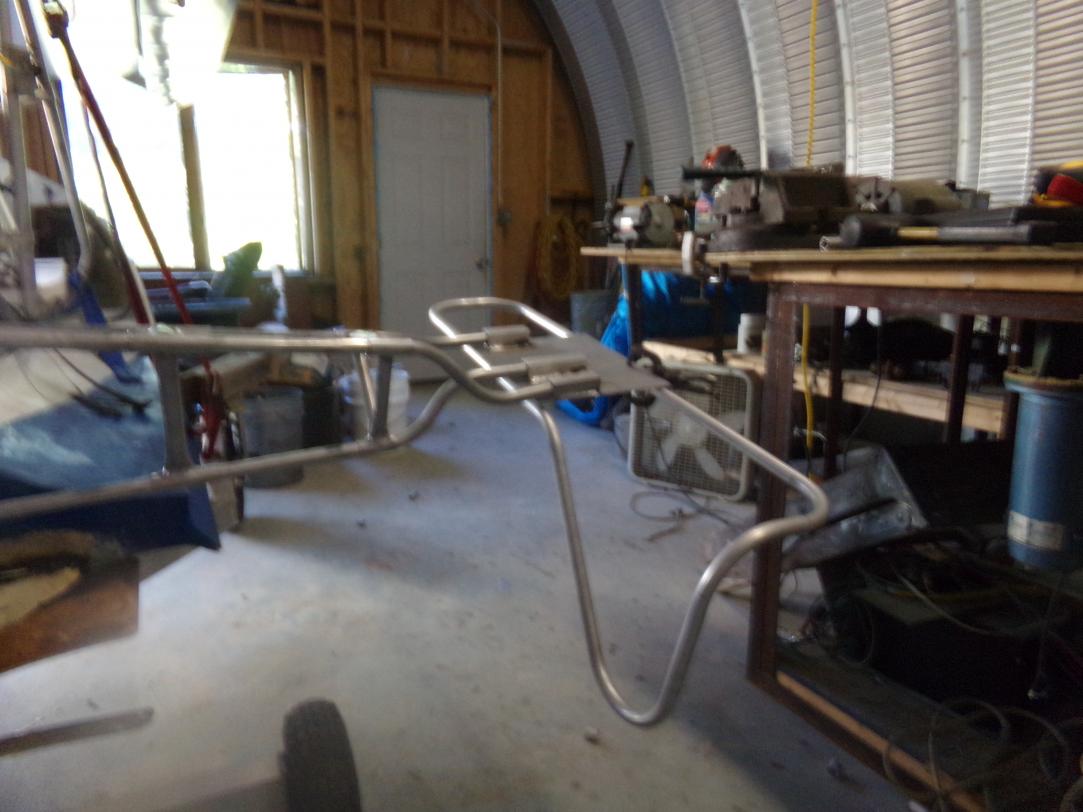
The new support frame work. After removing the old floats I weighed them .What was once under 10# now is 15
I do expect the remake will be less than 10
I'd like to point out all the compound angles and complex bends that make up the mount point these make a very good structure and have little give for the weight. this is better than the old setup. With the cable brace it works.
While most of the frame is identical The foam support skeleton is not but should be less and the reworked old floats have much more glass and resin. One might want less but often gets more. size and surface area will make the difference. I need to hold the same displacement.
Last edited by Norman Langlois; 10-05-2017 at 02:05 PM.
-
I have made changes to the angle of the floats . Static should have the tips up more and the inflight angle will be level on top with bottom at attack yet to be determined.
the portion of the float frame that projects down is a rest point and will be protruding from the main float. this part is always suffering gravel abrasion at the launch. The old floats were glassed over but quickly worn down to raw aluminum. I may panel and fill that part since it acts like a ruder in the water and if weight allows, may create an actual water ruder attachment here.
Last edited by Norman Langlois; 10-05-2017 at 02:00 PM.
-
-
Some numbers,this foam weighs 2# per cubic ft. these floats weigh 3.25# each and equal 202# of displacement. After coring they weigh 2lbs 10 oz. each. This is before expanded foam applied. I use a urethane foam as adhesive and filler. total weight to this point 8.25# with aluminum all support structure
-
Almost time to go north.
I have been looking at my other posts. I have another blog and not all viewers see everything since they are not equal. Here is a short landing video. I have been studying the angles, assuming we all see the same static image before you activate the video. The angles at touchdown. Landing and take off are the same planing attitude, power off landing power max take off with applied elevator.In previous posts and discussions . The forward hull angles were seen to be hindrance, the hull bump now removed.
Does anyone see anything wrong withe these lines and angles ?
-
Seems an awful lot of wing incidence when the hull is level. How does it look in level flight (cruise)?
Edit, I see in the other video it doesn't look that bad, but it sure sits way back in the water. Perhaps some more flotation aft would help? But it seems to do OK on the water.
Last edited by Dana; 04-08-2018 at 03:53 PM.
-
Thank you Dana
The static view angles are extreme . The above new float work is intended to reduce some of that. In the landing still view. I think the hull is level that is the main portion. I had thought the bow angle to be extreme ,now I think maybe not. I have no level flight to show. That which I have predates the as is. In the static the wing incidence is nearly 18 degrees. That does concern me , when wind conditions are unfavorable. When the plane is on step that actual angle is unknown. I assume it would be same as the landing. Excess power forces the nose down ,that makes some difference . Now that I have the elevator authority, that is not a problem. In level flight maybe 8 and 10 degrees to take off. I have made comments that what feels like level flight is difficult at full power it climbs. This wing has a negative 5 degree stall. A chart I was looking at stated that, and no stall all the way to 18 degree.
My early tests with the V-tail had a very high attack angle . It was difficult to control . The present does not .
I asked that if anyone see something wrong speak up and make a comment . Because I do plan to make an all new main hull. The angles appear to be correct. I wish only to change how the hull interacts with water during the transition to on step. this hull creates a significant bow wave . That I feel could be improved. It works it does not need to be changed but this hull needs to be replaced from hack and mod and water weight gain.
Last edited by Norman Langlois; 04-09-2018 at 09:00 AM.
 Posting Permissions
- You may not post new threads
- You may not post replies
- You may not post attachments
- You may not edit your posts
-
Forum Rules


 Reply With Quote
