-

Vision Microsystems VM1000 & EPI-800: How to Avoid the "MPT Blues"
This is the second in a series of informational articles on the Vision Microsystems EPI-800 and VM1000 Engine Management Systems. As a reminder, I’m not a certified avionics technician but an experimental aircraft owner and enthusiast like many of you. My intention with these posts is to pass along the information I’ve learned over the years to help keep your EPI-800 or VM1000 system alive and well, giving back to the community that has given so much to me. This writing will cover aspects of the manifold pressure transducer “care and feeding” to help you avoid the “MPT Blues.”
The VMS engine management system receives manifold pressure (MP) information from a manifold pressure transducer (MPT), VMS part number 3010015. The MPT receives 5VDC input from the VMS data processing unit (DPU) and returns a low level signal proportionate to the absolute intake manifold pressure. The DPU processes this signal to provide the cockpit indication of MP in inches of mercury. If properly installed and maintained, the MPT is a robust and reliable unit giving decades of trouble free service.
The MPT consists of an electrical sensing unit soldered to a PC board and this assembly attached to a machined aluminum block. The first generation units had a tan PC board with red-green-white-black wires; later units had a green PC board with four blade connectors. The sensing unit is a 0-15 psi absolute sensor with two sensing ports. In VMS installations, one port remains open to ambient pressure while the other is connected to a brass nipple in the mounting block, a snubber fitting to dampen pressure transients, and to the aircraft manifold via owner installed fittings.
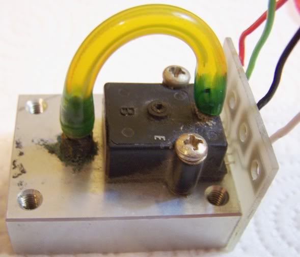
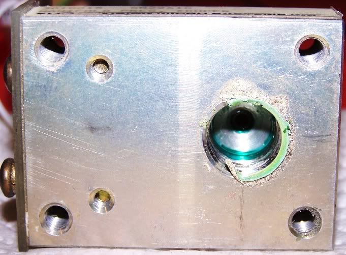
For longest service life, guidelines in the VMS installation manual must be followed. Specifically, it is essential that the MPT be mounted in a position vertically higher than the manifold pressure port on the engine. If the MPT is mounted level with the engine MP port, or worse yet lower than the port, it is possible for liquid fuel and/or heavy fuel vapors to condense and accumulate in the MPT assembly. Over time, the blue dye present in 100LL fuel accumulates and congeals contaminating the snubber, sensing tube, and eventually the sensor itself. Picture 1 below shows a MPT that came to me for repair with about 15 years time in service, the owner complaint was sluggish and inaccurate indications. The owner had also attempted to dismantle the unit himself breaking both the plastic sensor pressure ports in the process. Note the yellow pressure tube contaminated on both ends with blue dye. Also note the dye residue around the brass nipple and sensor ports. Picture 2 shows the bottom of the aluminum block where the snubber assembly (removed in this picture) and aircraft MP port are connected. Note the excessive amount of congealed blue dye inside the cavity. After consulting with the owner, I found that his installation was in the engine compartment and below the level of the engine MP port, the worst possible location; it is a wonder the sensor lasted as long as it did. On the test bench, as received the MPT provided an indicated MP of 24.1 inches when actual pressure was 30.15, in excess of 20% error. Makes one wonder how long an engine would hold up if it is consistently overpowered in cruise by 6+ inches MP?
The MPT has two basic failure modes, gradual and sudden. Sudden failure results in a cockpit indication of 00.0 MP with the engine running. This is usually caused by wiring issues such as a grounded signal wire, breaks or shorts, loose wires at the DPU terminal, etc. It can also be caused by complete failure of the sensing unit, although this is rare. Gradual failure is the more common mode. Gradual failure is characterized by slowly decreasing indicated MP over a period of time for a given throttle setting. It can be very insidious occurring over a period of weeks or months. Eventually the cockpit indication may be near zero or even negative MP at idle. The telltale way to diagnose this failure is to check the indicated MP on your VMS display against the local altimeter setting (if at sea level, or the altimeter setting corresponding to "0" feet if at higher elevation). The two numbers should agree within 0.2 in Hg, or about 0.5% if the MPT is functioning correctly; outside this range and you have an inaccurate sensor that needs to be repaired.
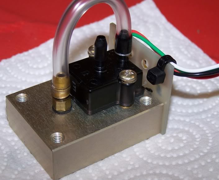
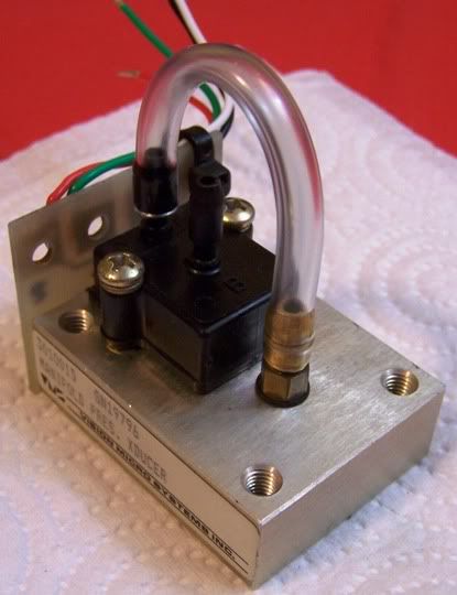
Now back to our poor old MPT that had to endure a life of hardship in the engine compartment. I did a thorough cleaning of the unit after dismantling all the parts. I removed and discarded the old sensor unit and replaced with new. FYI, you can’t use your "hardware store" soldering iron on the sensor unit. It’s very heat sensitive, the tech specs allow no more than 2 seconds contact at 482F requiring a highly accurate variable temperature soldering iron, precision tip, and special low temp/no acid solder. I know of owners who have shelled out $85+ for a brand new sensor, “glopped” on hardware store solder to get it to stick to the new sensor and PC board, then reinstall only to find it does not work; the sensor was internally destroyed by excessive heat and incorrect assembly procedures. Now back to the repair job: after I replaced the old sensor, I reassembled the MPT and replaced the old yellow tube with a clear tube making it easier to detect any blue dye contamination (see pictures 3 & 4 below). On the test bench this now “like new” unit is spot on to the local atmospheric pressure and the owner is happy to know with his new MPT and corrected installation, he should get at least 20 or more years of reliable service and accurate cockpit MP indications.
So, what can you do to help your MPT give you long and reliable service life? First, avoid the “MPT Blues” by making sure your installation is IAW the VMS VM1000 or EPI-800 installation manual guidelines. Never install your MPT in the engine compartment and never install lower than the engine MP port. Some owners have gone so far as to install a small lawn mower style clear plastic/paper element filter between the engine MP port and the line going to the VMS MPT, I don’t see this as necessary plus it introduces another point of possible vacuum leak, but others swear by it. During your annual condition inspection, take a look at the plastic sensor tube for indications of dye contamination. If present, check your MP line for any areas where residual fuel or vapors can condense and accumulate, correct your installation as necessary.
Next, remove the MPT for cleaning—be sure to discharge yourself to ground to avoid static electric damage to the sensor before starting work. After removing the MPT from the aircraft, carefully pull the plastic sensor tube from the brass nipple only, DO NOT try to remove it from the plastic sensor port or you will likely break it off. If the tube has become too hard/brittle to remove, use an exacto knife, score the tube longitudinally up the brass nipple, and pull it off the nipple. Remove the 4 screws holding the electric sensor/PC board assembly and set it to the side. You now are able to clean the brass nipple port and the MP port connection on the back side. Use a mild solvent such as mineral spirits, denatured alcohol, or acetone to dissolve the congealed blue dye. You can use a dropper to fill the pressure port, wait a few moments, and drain onto a paper towel, when it comes out clear, your port is clean. Try to clean both directions, i.e. pressure port toward snubber fitting, and snubber fitting toward pressure port. If you suspect excessive contamination inside the block, then disassemble the snubber and clean separately from the block. Gently blow out the port, allow to dry thoroughly, and reassemble. If the tube had to be cut, or if you cannot clean out the dye contamination, replace the plastic sensor tube with new. To remove it from the plastic sensor port, score the tube with an exacto knife as before and carefully remove.
Finally, get in the habit of comparing your altimeter setting to the indicated MP before engine start making it part of your power-on pre-start checklist (remember to correct for other than sea level airports). This will preclude you flying with an inaccurate MP setting and possibly overpowering your engine in cruise. If you are out in the middle of nowhere and notice a bad indication, you’ll at least have an idea of the magnitude of the error and be able to power conservatively until you can get somewhere for repairs.
Hopefully these tips will keep you and your MPT be happy for years to come, having no “MPT Blues” is a good thing! If I can help you with a manifold pressure transducer repair or any other Vision Microsystems issues, please don’t hesitate to contact me at mooney37v@juno.com
Happy Flying,
Reggie
PICTURE #1
PICTURE #2
PICTURE #3
PICTURE #4
Last edited by Glas467; 02-25-2012 at 07:13 AM.
Reason: Correction for higher elevation airports
-
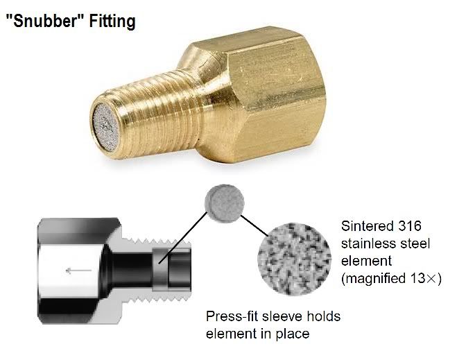
I have received several questions about the snubber fitting, what it is and what is does, so here's a post to clear that up. The snubber is a brass fitting with some kind of restrictor built into it. Typically the restrictor is in the form of a porous stainless steel insert (see attached picture). The porosity of the insert allows pressure equalization on either side of the fitting but dampens out pressure spikes or transients resulting in a smoother and more stable readout on the cockpit indicator. For those having issues with the MP indication jumping around, especially during power changes, the snubber fitting will usually solve the problem.
Happy Flying,
Reggie
Tags for this Thread
 Posting Permissions
- You may not post new threads
- You may not post replies
- You may not post attachments
- You may not edit your posts
-
Forum Rules


 Reply With Quote